
Introduction
Movement joints are often required in concrete structures to allow free expansion and contraction. Joints are usually provided in structures such as retaining walls, reservoirs, roads, and long buildings, etc.
Reasons for Provision of Joints
- Fluctuating movements due to diurnal solar effects, and seasonal changes of humidity and temperature.
- Progressive movements due to concrete creep, drying shrinkage, and ground settlement.
- Abrupt changes in loading or ground conditions which can affect the size or type of foundation.
- To avoid the formation of cracks due to shrinkage and thermal movements.
Types of Joints
Depending upon the purpose, different types of joints exist. The commonest joints are expansion and contraction joints. Other types of joints which exist such as sliding joints, butt joints, and keyed joints are usually equally provided in structures depending on circumstances. Table 1 gives a summary of the types of joints and where they are usually required in structures.
Table 1: Types of joints and where they are required in structures
| Type of Joints | Where required |
| Expansion joints | 1. Large areas of walls and roofs that are not protected from solar heat gain.
2. Where a contained liquid is subjected to a substantial temperature range. |
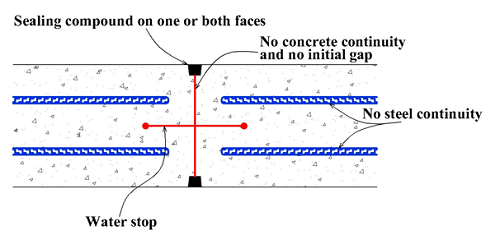
| Contraction joints | This can be formed by casting against stop ends or by incorporating crack-inducing waterstops. |
| Keyed Joints | For walls more than 1 m or 4 ft height to reduce the risk of percolation of moisture through the joint. |
| Construction Joints | In slabs laid on the ground (and not forming part of a foundation raft), construction joints should be placed as permanent joints in predetermined positions, such as at the end of a day’s work, at a restricted section, at a change of thickness, or at other positions where cracks are likely to occur. |
| Butt joints | Low walls with thin stem. |
How to Introduce Joints in Structures
Joints are introduced to counter cracks. The introduction of joints in structures first requires the proper calculation of joint spacing and also knowledge of the spacing of cracks. Three cracking conditions are usually considered in the design and construction of concrete elements: mature concrete, tension from bending, and direct tension as well as shrinkage/movement for immature concrete.
The crack spacing calculation usually follows the guidance based on the three conditions outlined above:
For mature concrete: cracking due to tension resulting from bending, design surface crack width (BS 5337) =

Where,
εm = is the average strain in the member at the level at which the crack width is being calculated,
αcr = is the distance between the point considered and the surface of the nearest longitudinal bar
cmin = the minimum cover to the tension reinforcement
h = Overall depth or diameter of section
x = Depth to the neutral axis
For mature concrete: cracking due to direct tension, certain deemed to satisfy requirements outline below in Table 2, apply.
For immature concrete: cracking due to restrained shrinkage and movements due to heat generated by hydration, design surface crack width (BS 5337) =

Where,
fct = average bond strength
fb = 1 for plain bars, 0.8 for type 1 deformed bars and 0.67 for type 2 deformed bars
ϕ = bar size
ρ1 = Proportion of total reinforcement in terms of gross section (= As/bh or Asc/bh)


Where,
w = total distributed service load per unit area (= gk + qk)
Position, Methods of Introduction and Materials for Joints
The position, method of introduction, and materials used for joints depend on the structure that would receive the joint.
Materials of Joints
Joints are usually introduced with the use of water bars. Water bars (or water stops) are barriers provided in the construction joint of concrete to prevent seepage across a point of weakness that the joint represents. Water bars can be pre-formed strip water bars, hydrophilic or swellable water bars, cementitious crystalline water bars, or injectable water bars. Besides the water bars, joints can be introduced with the use of rubber pads, neoprene, a membrane of PTFE (polytetrafluoroethylene), or some similar materials.
Position of Joints
Joints whether expansion or contraction joints can be introduced vertically or horizontally. Horizontal joints are common in structures such as buildings; retaining walls, bridges, etc. while vertical joints are common in water-retaining structures. There are also situations where joints can be introduced both horizontally and vertically in one structure.
In buildings, joints as wide as 25 mm (recommended) should be made at 50 m intervals or 25 mm in the top storey, open buildings, or exposed slabs. When joints are horizontally located, water bars should be positioned centrally within the wall section and on the underside of a floor slab, if it is supported on a smooth level layer of blinding concrete (see Figures 1 and 2). Generally, surface-type water bars should not be used because they will not prevent seepage unless it is rigidly supported from behind. If the joints in buildings would be permanent, it is necessary to carry the joint through the floors, roof slab, and walls above ground level in one plane. The joints in the walls should be made at the columns, in which case a double column is provided; the space is filled with a joint filler to prevent the accumulation of rubbish. In slabs and flat roofs, joints would be made through the use of double beams with the provision of water bars where appropriate. In finishes and claddings, joints should also be provided.


In vertical situations, water bars must be located on the internal face of a tank or reservoir (but on the external face of a basement where the intention is to keep ground-water out). Plain butt-joints are preferable, unless it is necessary to transfer shear across the joint, in which case a joggle may be required which would also provide a potential point of weakness if adequate care is not taken when introducing it.


In bridges, expansion joints are commonly introduced taking care to ensure that it allows proper drainage and does not impair riding quality. The type of joint used in bridges depends on the size of movement expected. For small movements, a type of joint commonly known as an asphaltic plug which consists of a small gap covered by a galvanized steel plate, and a band of rubberized bitumen flexible binder is used to replace part of the surfacing. For larger movements, a flexible sealing element supported by steel edge beams is required while for very large movements, mechanical joints based on interlocking sets of steel-toothed plates can be used.
Methods of Construction
Method of construction comes in place when there is some difficulty in using any common type of joint. In this situation, it is common to use monolithic construction. However, in situations where it is necessary to provide for an amount of expansion exceeding the probable amount of shrinkage, a space, say 12 mm or 0.5 inches wide, should be left between the faces of the concrete and filled with resilient material. If the floor is subject to abrasion, as in factories where wheeled containers travel across the joint, the edges should be protected by steel angles.
Qualities of Good Joints
1. It should be designed to require minimal maintenance during its lifetime.
2. It should be such that it can be easily replaced when necessary.
Source
Reinforced Concrete Designers Handbook by Reynold and Steedman (10th and 11th editions).